By Lorenzo Barbieri and Gaetano Brando
Abstract: Radio meteor observations have been practiced by few observers in the amateur community using different and sometimes complicated techniques. Based on the experience with RAMBo, the authors have created a device using SDR (Software Defined Radio) technology which measures and records the main physical parameters of the radio meteors by analyzing the meteor radio echoes. The low cost combined with the simplicity of the construction and management makes it suitable for the creation of a global network of receiving stations capable of producing coherent observational data which can be analyzed to study meteor shower activity.
Introduction
Almost everything we know about meteors is due to centuries of visual observations. While the ancient observational “reports” date back to the 3rd century BC, it was at the beginning of the 20th century that the observation techniques were based on a standard. This allowed to overcome the subjectivity of the individual observers as well as the difference in observing circumstances, making it possible to put together a large amount of data from all over the world recorded at different times and at different places.
The availability of cameras with wide-field optics which allow video observations resulted in a new observational technique with a number of new standards, such as Metrec, UFO, CAMS, Global Meteor Network as main players which are not entirely compatible with each other but allow to compare observational results.
So far, the observation of meteors by amateurs in the radio field has been characterized by methods and techniques that were often different, depending on the skills and interests of the individual amateur observers.
The project that we introduce here has the ambition to start defining a proposal for a common technique and observational standard applicable in this field.
The radio meteors
When a body (meteoroid or debris), after travelling for millennia in interplanetary space, enters the upper layers of the Earth’s atmosphere it collides with the upper molecules of the atmosphere it encounters along its path. The speed of these particles moving within the solar system, relative to the Earth, is very high, from a minimum of 12 to a maximum of 72 kilometers per second.
Regardless the small mass of the meteoroid, usually a few grams, its kinetic energy is definitely high. The kinetic energy is defined as:

With the exception of the rare cases in which the meteoroid is of a large mass, after a very rapid increase in temperature the entrance in the atmosphere usually results in its disintegration.
This process causes the emission of light and the disruption of the electrons in the atoms, forming a cylindric tube of free ions and electrons dispersed along the trajectory of the particle in the atmosphere. The first phenomenon is commonly known as a “meteor” or “shooting star”.
The cylinder of free ions and electrons can be dense, depending on the kinetic energy of the impact, and more or less persistent, since ions and free electrons tend to recombine immediately.
When free electrons are hit by an oscillating electromagnetic field they are induced to oscillate with the same frequency. This oscillation in turn involves the re-emission of an electromagnetic field and if this oscillation is in phase for a large number of electrons there is a radio electric transmission that can be detected from a distance.
Therefore, if a cylinder of free electrons generated by a meteor phenomenon is hit by a radio electric transmission, then it behaves or at least in a small part of it, as a reflector of this transmission. This reflection lasts until the moment of dissolution due to the recombination of ions and electrons.
The minimum required linear density of a radio meteor is defined by Belkovich (1972, 2006):
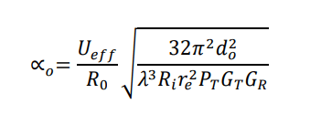
Where:
- Ueff is the sensitivity threshold of the receiver;
- R0 is a factor that statistically groups the observability of the radio meteors due to: radius, diffusion and speed of the meteor, also calculated along the direction of the maximum antenna sensitivity;
- do is the distance in meter between the receiver and the meteor area along the direction of the maximum antenna sensitivity;
- λ is the wavelength;
- Ri the receiver input impedance (in Ohm);
- re is the electron radius;
- PT is the transmitting power (in Watt);
- GT and GR refer to the antenna gains.
It is important to note that the wavelength λ is in the denominator and in the cube.
It is obvious that if the wavelength decreases, the minimum threshold for the detectability of a radio meteor increases, making reception more difficult. This point will be explained further in this article.
If a VHF transmitter is continuously transmitting with an emission pointed upwards and a receiver is tuned at the same frequency at a position on the Earth surface below the horizon for the transmitter, the receiver can detect the transmitted signal when a cylinder of free electrons is generated by a meteor, creating the reflection conditions (Figure 1).

Figure 1 – Radio meteor reflection scheme.
When this signal is being recorded by a receiver, we speak about a “radio meteor”.
As already mentioned, a radio meteor is a reflection phenomenon of an electromagnetic signal and is subject to the physical laws that govern these phenomena such as the condition that the entrance angle is equal to the reflection angle. We will consider these characteristics at the end of this article.
Receiving radio meteor echoes
Unlike visual meteors which are only visible at night and for which the observability is heavily influenced by lunar illumination, light pollution and weather conditions, radio meteors are continuously detectable. The recording of meteor radio echoes can only be disturbed by echoes caused by airplanes, satellites or by reflection on the sporadic E layer.
Since the second World War, radars have been built to study radio meteors. Generally, there are two types of radars, “forward scatter” and “back scatter”, depending on the position of the receiver with respect to the aiming of the transmitter. In the first case the receiver is placed very far from the transmitter, hundreds of kilometers, receiving reflections generated halfway between the receiver and the transmitter. In the second case, the receiver is close to the transmitter and captures the reflections backwards.
Among the many examples of meteor radars, we can mention the one of Vedrana di Budrio (Bologna) owned by the CNR which was in operation in the 1990s or another currently active radar, the Canadian CMOR located in Ontario.
Meteor radars are devices that consists of transmitters that emit pulse signals combined with a set of receivers equipped with directional antennas working as interferometers in order to reconstruct speed, position and the direction of the meteor which indicates the radiant.
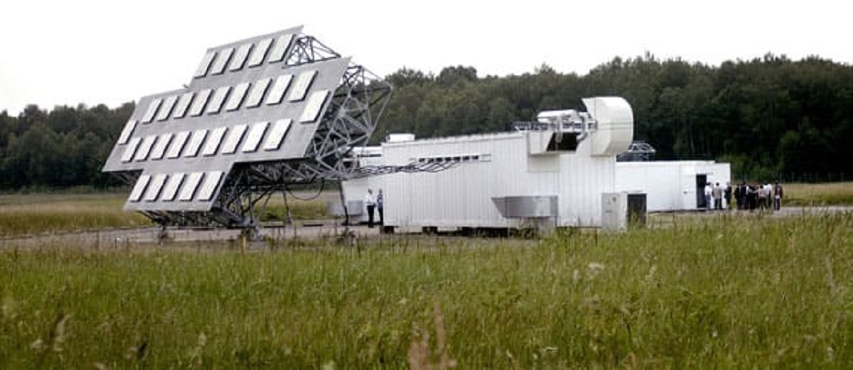
Figure 2 – The military radar at Graves, near Dijon, France.
These data allow to know the orbital elements of the meteoroid which make it possible to identify a possible association with known meteoroid streams. Meteor radars are therefore complex and very expensive devices only available for professional research projects conducted by scientific institutions or universities. The amateur community, amateur astronomers as well as radio amateurs, has explored this technique with various experiences. For instance, the transmission of communications beyond the Earth’s curvature, using the moments when a radio meteor allowed reflection and transmission of the communication.
Obviously, no amateur can afford the purchase and operation of such a powerful transmitting device, therefore the amateur community must make use of other available transmitters such as radio or television transmitters, military radars, amateur radio beacons, etc.
The radio meteor observing is usually done using a normal amateur radio receiver tuned in SSB mode (Single Side Band) about 1000 Hertz separated from the carrier of the broadcast signal. This technique allows to listen to an audio signal at the output of the receiver at a frequency equal to the difference between the received signal and the frequency tuned on the radio.
In the case with 1000 Hertz, the audio output generated sounds like a whistle that emerges from the noise from time to time, whenever a radio meteor reflection is received. This whistle has intensity and duration proportional to the size of the cylinder with free electrons, and to the ion-electron recombination process duration.
Sometimes dedicated software’s are used which graphically represent the audio signal creating the so-called “waterfall”, usually in false colors, which is a method that displays the amplitude, frequency, and duration of the audio signal on a video monitor.
Amateur radio meteor observing almost always ends here, just simply listening to the received signals.
Counting and measuring radio meteors
Within the Associazione Astrofili Bolognesi we asked ourselves whether it was possible to go further than just listening and to make measurements capable of investigating the activity of meteor showers using an amateur level approach.
Obviously, the kind of tools available to the amateur community impose great limitations. First, the absence of a pulsed signal transmitter prevents both the measurement of position and direction; in other words, even if there were several receivers arranged in various ways on the Earth surface, and even if they could be connected, triangulation would not be possible. Once the idea to obtain the orbital elements for the individual meteors had been given up, only the instant of the event, the amplitude of the generated audio signal and the duration of the event of each radio meteor detected remained as possible measurements.
With these data, it is possible to make an analysis of the activity level (hourly rate) and to evaluate the kinetic energy and the mass-distribution of the recorded meteors. This kind of observation requires to listen continuously, to digitize the signal and to record it in function of the requirements for a physical and statistical analysis. Given the need for continuous operation for the purposes of digitization and recording, we have discarded the use of personal computers when looking for dedicated hardware.
The RAMBo experience
RAMBo (Radar Astrofilo Meteorico Bolognese) uses the signal emitted by the military radar transmitter Graves located in France which continuously transmits in the VHF band at very high power (the frequency is 143.05 MHz) (Figure 2).
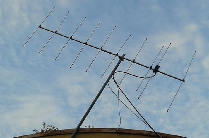
Figure 3 – Vertically polarized Yagi antenna.
Its transmission is directed upwards and because of the shielding by the Alps, it is not possible to detect it directly from Bologna.
Our receiver has a 10-element Yagi directive antenna (Figure 3) pointed in azimuth in the direction of the transmitter and at about 25° elevation, where we calculated that the reflection point with the upper layers of the atmosphere should be. The radio receiver we used is a Yaesu FT 857. The receiver audio output is amplified with an operational circuit, split into two outputs. One of the two is squared off to measure the frequency, while the other is dedicated for an amplitude measurement. These two signals are sent to a microprocessor (Arduino) programmed by the authors. The frequency, duration and amplitude are measured by Arduino, the instant of the event is recorded, and the results are written in a log file consisting of records with the data for each meteor event.
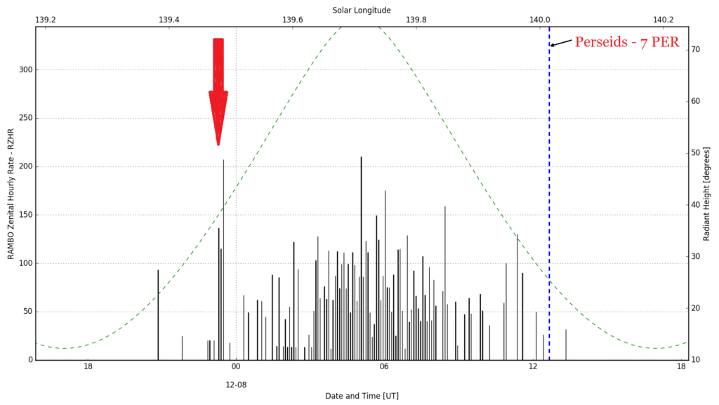
Figure 4 – Perseids 2016.
After a few months of experiments, we were able to improve both the hardware and the software in order eliminate completely the many “false positives” that an AM (amplitude modulation) reception normally creates.
For this purpose, we used the microprocessor as a frequency meter. If several consecutive samples occur in a narrow range around the tuned frequency, we can reasonably assume that it is a meteor.
If the frequencies of consecutive samplings are random, the echo is discarded.
The experience with Rambo was very satisfying. With this project we have recorded and measured almost a million meteors every year since 2014 up to today.
We have calculated the RZHR of many showers and we have detected the filaments of some meteor showers. We have used this data for presentations at two editions of the annual conference of the International Meteor Organization and we published some articles (Barbieri, 2016; Brando, 2016; Barbieri and Brando, 2019).
As evidence for the possibilities of RAMBo, we mention the observations concerning the 2016 Perseid shower: some days before the Earth encounter with this well-known meteor shower an astronomical telegram (CBAT) was issued by P. Jenniskens (2016), analyzing the perturbation on the meteoroid stream by the major planets and predicting the possible presence of a filament a few hours before the shower peak activity at solar longitude 139.5°, or around midnight on August 11–12.
Indeed, as can be seen from the graph in Figure 4, the filament was detected by RAMBo on August 11 at 23h20m UT. It should be noted that the duration is about three sampling intervals; each sampling interval being 5 minutes long, the total duration of this meteor shower filament was about 15 minutes.
From this data we can roughly extrapolate the dimensions of the filament: since the Earth moves at about 107000 km/h in interplanetary space. From

we find that the diameter d will be larger than 107000 × 0.25 = 26750 km, depending on whether the Earth has intersected the dust filament perfectly in the middle or more or less laterally.
The data collected during a period of time is published dynamically on a page of the website of our Association and archived weekly.
The limits of the RAMBo experience
Despite the fact that this project has given us a lot of satisfaction, RAMBo also met some limitations.
- First, this project is difficult to reproduce. The sound card is our prototype, its assembly and its use require knowledge of electronics which is not common for all amateur astronomers. The same should be said for the Arduino programming.
- Another drawback is that the equipment isn’t cheap. The radio which we use is extremely expensive and other similar devices are even more expensive.
- Finally, the measurement is taken from an audio signal generated by the radio. We may assume that it could be roughly proportional to the actual radio electric power of the received signal, but we cannot be certain of this at all. If you want to think in terms of radar, you must measure the radio electric power received by the antenna directly.
For these reasons we have tried to develop a receiver that overcomes these three limitations, and to achieve this we have explored the world of SDR.
What is SDR (Software Defined Radio)?
A radio device as we know it historically can be defined as a set of analogue components each of which performing a certain function. For example, if we think of the classical superheterodyne radio, inside of this we find an input amplifier, a local oscillator, a mixer, a band filter, an intermediate frequency amplifier, a double half-wave rectifier and a detector.
All these functions, although performed by analogue devices, are mathematical functions: to remain with the basic functions listed above, these functions are multiplications, divisions, subtractions, application of trigonometric functions, integrations, etc. As we known, to multiply, to subtract, to divide, to generate sinusoids or to integrate and to derivate, it is much simpler and more efficient today to use a computer rather than an analogue circuitry.
The SDR (Software Defined Radio) in fact performs these functions once the antenna signal has been digitized, it is computer processed by using dedicated algorithms. This way the PC works like a radio. The first studies on SDR date back to 1970 in the USA and the first SDR transceiver was made in Germany in 1988. Today the SDR devices can be found in every television, digital radios (DAB) and smartphones.
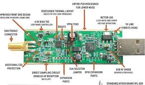
Figure 5 – This chip is commonly implemented in the small circuit called the “dongle” shown here.
In the 2000s, the advent of the RTL2832U integrated circuit made it possible for thousands of amateurs and enthusiasts to access the world of digital radio. This chip is commonly implemented in the small devices called “dongles” such as shown in Figure 5. The connector for the coax cable coming from the antenna is visible on the left side and the USB plug to connect to a computer is on the right side.
We have tested a few and we think that the NooElec NESDR Smart v4 SDR is the best. It costs 32 euro, it is stable, reliable and it is the one with the lowest background noise among those we tested. With this very cheap device, any enthusiast can make a receiver using a personal computer.
Detecting radio meteors with the SDR
Like all software-based applications, not all industry development is industrial and patented. There is also an open-source niche (GNU Radio).
Using this environment, after more than a year of attempts we were not able to build a project that met the expectations we had in mind and this failure led us to give up.
The turning point that led to the resumption of the study and the realization of the project was the discovery of a Python programming language library specially written to operate the integrated circuits RTL2832U and R820T2, which are the heart of the “dongle”. We have therefore written a Python application that performs the work of tuning the dongle to the frequency of the transmitter chosen by the user, setting the gain, sampling the signal, and performing the FFT (Fast Fourier Transform), thus obtaining the frequency and the amplitude of the received signal. It should be emphasized that this way we obtain the exact measurement not only for the frequency, but also for the radio electric signal power. Unlike all previous experiences based on listening at the audio output, this configuration is comparable to a real radar.
Once these two quantities have been obtained, our application is able to recognize the meteor echo by eliminating false positives both due to satellites or airplanes and to weather transients such as lightning and to anthropogenic transients. The output file allows you to see the shape of the echo profile of the recorded meteor and the frequency of each individual event. After the first successes obtained using a personal computer, we tried to run this application on a small and cheap microcomputer like the Raspberry. The result was that the execution speed doubled, further improving the application performance.
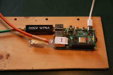
Figure 6 – Carmelo.
We have thus created an extremely economical device, easy to assemble and to manage: hence the name CARMELO stands of Cheap Amateur Radio Meteor Echoes Logger (Figure 6). Carmelo is very reliable. After months and months of uninterrupted operation with three units there has never been any interruption or any failure.
First results
The first months of operation showed us Carmelo’s potential.
In Figures 7 and 8 you can see the time on the x-axis and the signal to noise ratio (SNR) on the y-axis. Figure 7 is a typical example of an “overdense” radio meteor, i.e., an event in which the cylinder of free electrons is sufficiently dense to behave like a solid body. Its reflection shows a very rapid rise, a flat saturation trend and a descent due to the dissolution caused by the ion-free electron recombination.

Figure 7 – Typical shape of an overdense meteor.
Another type of reflection is the “underdense” radio meteor, generated by an impact with lower kinetic energy and therefore characterized by a low-density reflecting cylinder (Figure 8).
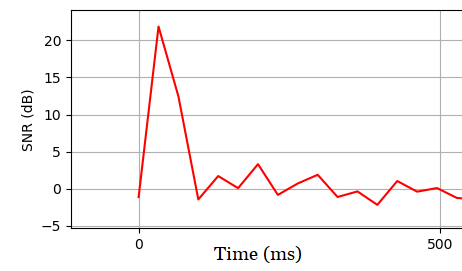
Figure 8 – Shape of an underdense meteor.
Note that the difference between these two cases is not limited to the shape of the profile and duration but also the difference in amplitude is evident which is in these cases 20 dB, a factor of 100 times. Figure 9 shows the distribution of all the radio meteors recorded in a single week; the x-axis displays the time, the y-axis the SNR while the size of each single dot is proportional to the duration.
The page shows in real time the individual recordings sent by each receiver wherever it is located. The only required condition is that the receiver is connected to the internet.
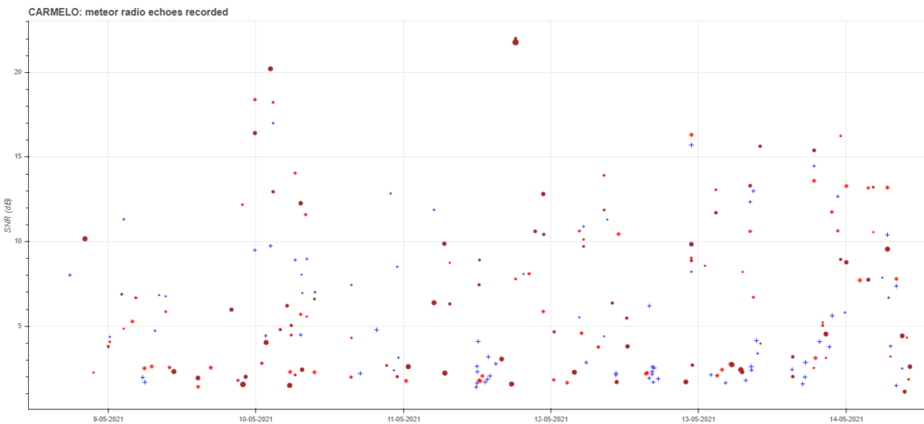
Figure 9 – Radio meteor echo events recorded by three Carmelos in one week. The three receivers can be identified by the different symbols that identify each of them. This image is taken from the web page .
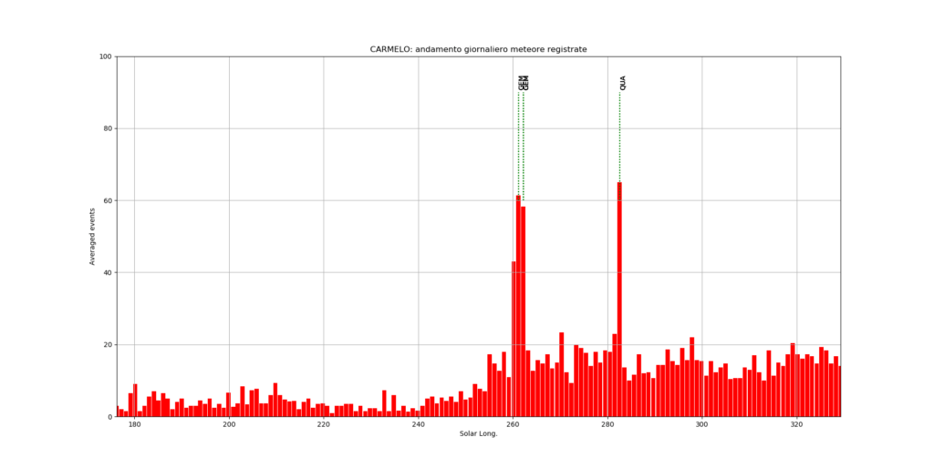
Figure 10 – RHR (Radio Hourly Rate) made with only three observing systems.

Figure 11 – Radio echo profile with an exceptional long duration.
Hovering the mouse over an event on the webpage, you can read the data related to the recorded radio meteor (date and time, location, amplitude and duration of the echo), clicking on an event displays its reflection profile.
Despite the small number of receivers built and put into operation so far, it is already possible to understand the potential of a recording made with a large number of receivers located throughout a large area. To show this potential we have created Figure 10 which shows the computed RHR (Radio Hourly Ratio) covering the time span autumn–winter 2020. The Geminid and the Quadrantid meteor showers are very evident.
The three receivers used so far are all tuned at the frequency of the military transmitter Graves, located near Dijon, France.
This transmitter has an advantage and at least two disadvantages:
- the advantage is that it transmits at very high power and this makes it suitable to be used by receivers located hundreds of km away;
- the first disadvantage is that its frequency (143 MHz) is much higher, at least three times, than the optimal frequencies for receiving meteor radio echoes and this decreases the efficiency of the system, as we have seen in the introduction;
- the second significant disadvantage is the fact that, as a radar, its beam scans the sky with a fixed periodicity thus generating an alternation of intervals during which the signal is receivable and intervals when the signal is totally absent.
Symbolic of this situation is the echo caused by a huge meteor event on 2021, April 2 with a duration exceeding half a minute (Figure 11). The profile of this long persistent echo shows the intervals in which the radio meteor reflects the signal and the intervals during which it reflects no signal. As you can see, the transmitting radar sweep period is approximately 4.8 seconds (marked in green on Figure 11).
This means that if a meteor appears in an interval during which Graves does not transmit a signal towards the area of the meteor, it will not be detected. Moreover, the shapes of the echo profiles we measure, the amplitudes we calculate and also the recorded durations are strongly influenced by the oscillating behavior of the transmission.
In this regard, there are two considerations to be made:
- The first is that only with a reception like that of Carmelo, which is defined by the measurement of the radio electric power received instead of the audio of the radio receiver, it was possible to notice this characteristic of Graves. Years of experience with RAMBo did not provide this insight which is so obvious in a single echo profile generated by Carmelo.
- The second consideration is that a transmitter dedicated to the purpose of meteor observing, operating at lower power but with a suitable frequency and continuous emission, could lead to excellent results for hundreds of receiving stations. The progress in electronics makes this idea much more affordable than in the past.
A next test that should be carried out in north-western Europe, could be to receive the signal from the Belgian meteor transmitter BRAMS (Belgian RAdio Meteor Stations). BRAMS is transmitting at 49.97 MHz.
A global Carmelo network
There are at least three considerations that lead us to suggest the creation of a network of receiving stations based on a standard registration on a global scale.
The first consideration is that the sensitivity of a SDR dongle is lower than that of an amateur radio receiver. The data in our possession does not allow us to quantify this difference at the moment, but we can assume that it could be considerable.
Furthermore, the sampling frequency carried out with the mini computer is not particularly high with one sampling every 33 ms, which is longer than the duration of short underdense meteors.
Therefore, we do not expect a quantity of received radio echoes equal to those recorded with the RAMBo equipment with about one million radio meteors every year.
While with RAMBo the underdense radio meteors were the majority (90%), with Carmelo these are significantly less present, while the overdense ones prevail.
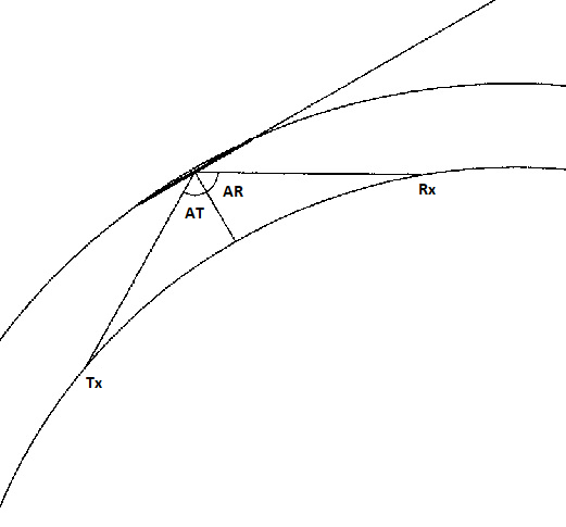
Figure 12 – Reflection geometry.
The result is a lower presence of sporadic meteors and a greater portion of those with larger mass and therefore presumably related to meteor showers.
More receivers placed at different distances from the transmitter can guarantee better coverage and a high number of received echoes.
A second consideration, as already mentioned in the introduction, unlike visual meteors that can be seen from any position on the surface as long as the light emission is sufficient to be detected, the same condition does not apply to radio meteors.
As a radio meteor is a phenomenon due to the reflection of an electromagnetic emission, the reflected ray must have the same angle AR as the transmitted one AT (see Figure 12). Therefore, the echo from a radio meteor can be received only if the receiver is located at a position that complies with this condition. In another configuration the reception cannot take place.
Consequently, receiver stations located at different positions will detect different radio meteors and therefore only a network of observers spread over a large area can aspire to collect a considerable share of the radio electric echoes that can be received within that region.
Another consideration could be added. The cylindric shape of the reflecting tube let us assume that the reflected signal with the angle equal to that of the transmitted signal can be considered on a plane.
The line joining the points Tx and Rx on the Earth’s surface is orthogonal to the direction of the origin of the meteor, which is the direction or azimuth of the radiant (Barbieri, 2016). If two receivers detect the same echo simultaneously, they would then identify this line. In this case, we would obtain important information because knowing the position of the transmitter, we might be able to derive the trajectory of the meteor, a fundamental information for the association with a meteor shower.
Similarly, but in another way, Jean Marc Wislez (2006) describes the ellipsoid in which the transmitter and receiver are in the foci and the meteor’s trajectory is tangent at the point p. In the case of reception at two different locations there will be two ellipsoids intersecting with the point p in common.
Sasa Nedeljkovic (2006) tackled the geometry of this particular case with the aim to derive the trajectory of the meteor that produced the radio echo. These considerations let us assume that with a large network of receiving stations distributed over a large area, the challenge to obtain the trajectory of radio meteors that we had initially excluded from the possibilities of amateur radio meteor observing will once again become an intriguing subject of investigation.
These considerations are true only if we assume that the shape of the meteor ionized cylinder does not change over time.
But the shape of the cylinder could be distorted by the high-altitude winds. This could create multiple echoes, consequently the same meteor could be seen by multiple receivers.
A third and final consideration, as mentioned in the introduction, observing radio meteors has an undeniable advantage because it is always possible uninterruptedly, regardless of weather conditions and light pollution.
The only limitation, as for all astronomical observations carried out from the ground, is imposed by the horizon. Any observer can only observe visual meteors or radio meteors when the radiant is above or near the horizon.
Therefore, some meteor showers are observable from one hemisphere but not from the other or vice versa. Also, the observability conditions for the same meteor shower change, for a given receiving station, from year to year depending on the time when the activity peak occurs.
A global network of receiving stations all over the world capable to observe continuously with the same standard is able to overcome these limitations by ideally performing as a global terrestrial receiving station travelling in the interplanetary space with a 360 degrees field of view.
For the three conditions listed above, a global network of receiving stations based on a common standard is therefore highly desirable. Using Carmelo, this is also easily achievable. The data produced today is collected, processed and displayed on the website and is publicly available to the meteor observing community. Its eventual realization is based on the availability of individual amateurs, radio amateurs, educational institutions, research institutions or simple curious citizens to host a simple, economical, robust and reliable receiver.
What is needed to build a receiving station for radio meteors in the global network?
First of all, it is necessary to identify a known transmitter which is in continuous operation on the VHF (Very High Frequency) radio band. This transmitter must emit on a known frequency and must be tens or hundreds of km away from the receiving station and preferably be below the horizon.
Therefore, it is necessary to have an observation site as free from obstacles as possible. Most obstacles are man-made artificial objects but natural steep mountains in the immediate proximity can also obscure the observation horizon.
The best location can be the roof of a building, but it can also be a large garden if there are no buildings close to it. Otherwise, if the receiver is installed at some of the lower floors of a high building, this will undo the global coverage (360°).
The choice of the antenna and its correct installation should in no way be underestimated. This is where the effectiveness of the radio meteor detection is determined. There are two types of antennas: directional and omnidirectional ones.
In the first category we mention the Yagi type antennas (see Figure 3), in the second the collinear antennas (Figure 13).

Figure 13 – Collinear antenna.
For those who are completely uninformed about antennas we can say that if we listen with an omnidirectional antenna, it is as if we were looking at the starry sky with the naked eye, seeing many stars in a very wide field of the sky. If we listen with a directional antenna, it is as if we were looking at the sky with binoculars or a telescope, seeing a much smaller portion of the sky but with fainter stars than those visible to the naked eye.
Out of the metaphor: an omnidirectional antenna has a low and fixed gain, while a directive antenna has a higher gain but only towards a certain direction. The characteristic of the construction of the directional antennas determines the higher the gain, the smaller the area at the sky covered.
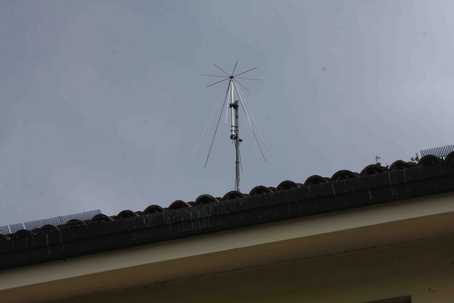
Figure 14 – “Discone” antenna.
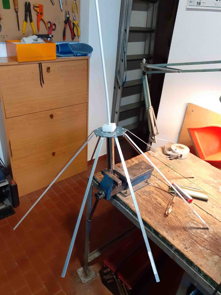
Figure 15 – Self-built ground plane antenna “Carmelina_143”.
Although most of the radio meteor observations are commonly made with directional antennas generally pointed in the direction of the transmitter and at a certain angle to the vertical, we suggest to use the vertically polarized omnidirectional antennas for the following reasons.
- First of all, this type of antenna is easier to assemble, less bulky and less critical in windy areas.
- Furthermore, omnidirectional antennas, in the case of a network distributed over a large area, allow a better comparison between individual receiving stations because it is independent of the gain in the antenna and it provides more comparable results for any possible triangulation.
- A third reason is the cheapness of the antenna. The omnidirectional antennas available on the market can be of various types, ranging from “discone” antennas, which cost is around 80 euro, up to balcony antennas that cost less than 30 euro.
Self-construction should not be underestimated at all. The self-construction of a “ground plane” type antenna has two advantages. First of all, it is very cheap, since it can be built for a few euros (Figure 15).
Moreover, it seems absurd but it is not, its efficiency is better than the commercial ones. The explanation for this apparent contradiction can be justified as the commercial antennas are almost never designed to operate on a single frequency but are produced and sold to allow radio amateurs to receive (and transmit) on many channels.
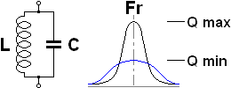
Figure 14 – “Discone” antenna.
An antenna is equivalent to an LC circuit which electrical characteristics determine the frequency on which it resonates.
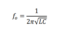
- fo is the resonant frequency (in Hz);
- L is the inductance (in H);
- C the capacitance (in F).
A “pure” LC circuit has a narrow and high Gaussian curve of the Q factor (similar to gain) on the main frequency (Figure 16).
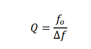
Q is the merit factor, comparable to the antenna gain and is the bandwidth.
A “loaded” LC circuit distributes the gain on a larger basis, the Gaussian is much wider, thus allowing us also to tune effectively on the adjacent frequencies, but the Gaussian is also lower and therefore loses gain at the main frequency.
Commercial antennas are also designed to transmit and this is the feature that affects most of their price due to the required construction accuracy, for simple reception no sophisticated antennas are required. To confirm the aforementioned reasons, a homemade ground plane like the “Carmelina_143” (Figure 15) proved to be more performant than all the other commercial omnidirectional systems that we have tested.
Once the antenna is mounted, a coaxial cable is required to connect the receiver to it. This should be a normal coaxial cable rg58 type or similar, suitable for VHF. We advise to use a cable as short as possible, both to save money, to minimize losses and to keep the signal to noise ratio (snr) as high as possible. The connectors at its ends must be on one side a male “SMA” to connect to the dongle and on the other side a connector suitable for the chosen antenna, in most cases this is a male “pls”. These can be purchased at specialized shops and via the internet, including adapter, for a few euro.
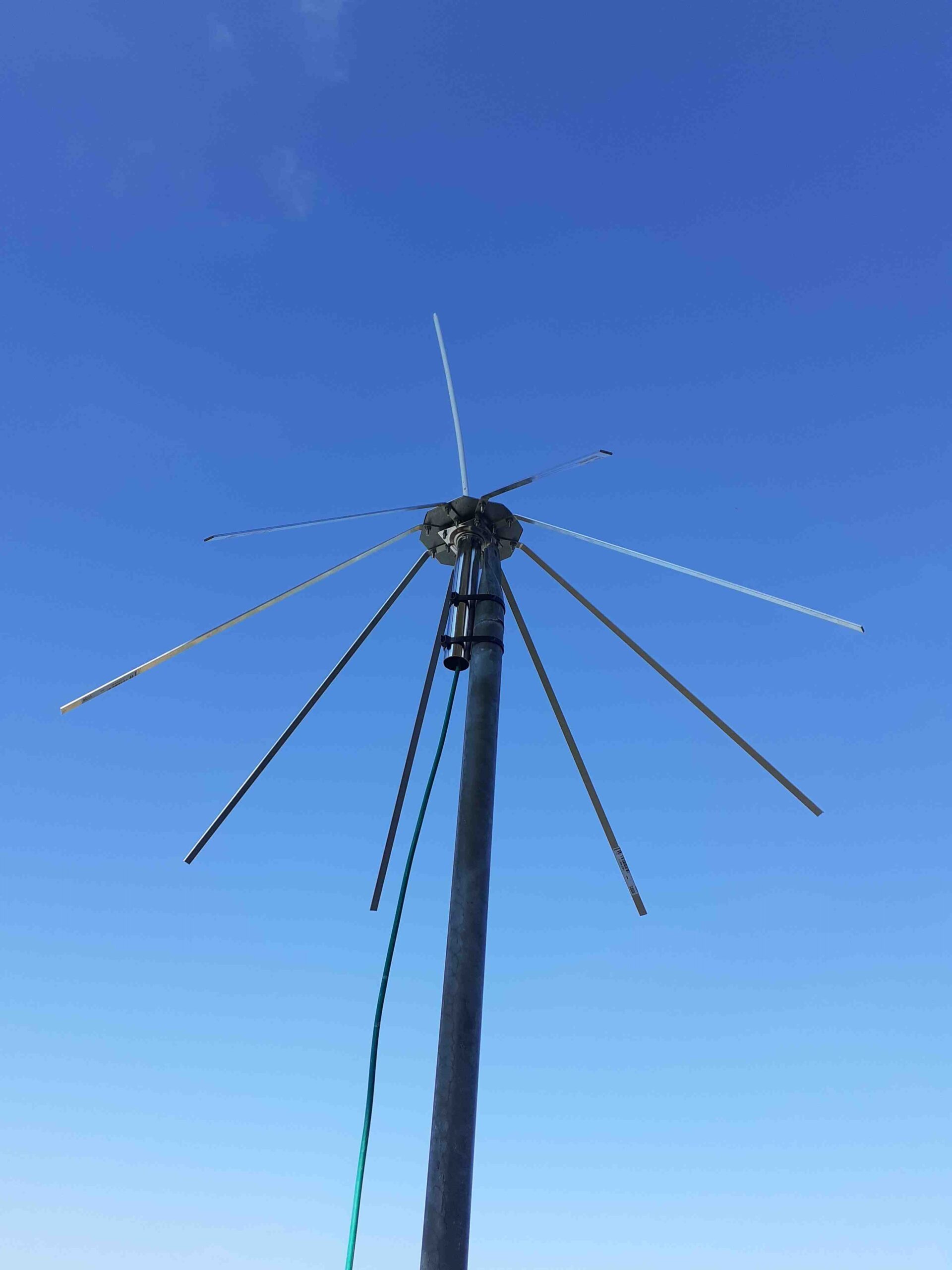
Figure 17 – Testing of the self-built ground plane antenna.
The dongle must be based on the integrated RTL2832U. We have tested a few models and the one we recommend is the NooElec NESDR Smart v4 SDR, it costs 32 euro, it is stable, reliable and it is the one with the lowest noise among those we tested.
As mentioned, the minicomputer adopted is the famous Raspberry Pi 4B, 2GB. This works fine. A SD card must be placed in the RPi. The available volume does not matter, the software (operating system, program and libraries) takes up only 3 Gigabytes.
The Raspberry Pi must be powered with a 5V power supply with USBc socket (i.e., the one for second-generation smartphones). Carmelo absorbs about 75 milliamps which at 5 v means a power of less than 400 mW. This is comparable to some small LED flash light.
Then, you need a LAN network cable that connects the RPi microcomputer with a router that allows access to the Internet. This cable can also be particularly long, indeed the advice we give is to place Carmelo as close as possible to the antenna and to reach the router with a network cable of the required length.
We have not enabled the wireless function on the Raspberry. After all, Carmelo is still a radio receiver and the fewer transmissions there are in the immediate vicinity, the better.
The total cost of these purchases is about 200 euro.
The software
The hardware is simple, cheap and common. What transforms this hardware into a real miniature meteor radar is the software.
Carmelo requires the following:
- The installation of the operating system, the simple and light version of Raspbian is fine.
- The Python libraries and our program, of course free available.
- A small csv file containing the data of the receiver radio station such as the location, geographic coordinates, frequency on which the receiver works, the type of antenna used, the symbol and the color to identify the observations from this receiver in the overall data visible on the appropriate page of the website.
Interested to join this project?
Visit our website and we’ll be happy to answer any questions you may have.
References
Barbieri L. (2016). “An antenna, a radio and a microprocessor: which kind of observations are possible in meteor radio astronomy?”. In Roggemans A. and Roggemans P., editors, Proceedings of the International Meteor Conference, Edmond, the Netherlands, 2-5 June 2016. IMO, pages 26–30.
Barbieri L. and Brando G. (2019). “Concerning the height of meteors”. WGN Journal of the IMO, 47, 108–115.
Belkovich O. I. (1971). Statistical theory of meteor radar observation. Kazan University, Russia.
Belkovich O. I. (2006). “Processing of radar observation 1: Sporadic background, detection threshold, radar sensitivity”. In, Juan Martine Semegone, Pavol Zigo, and Cis Verbeeck, editors, Proceedings of the Radio Meteor School, Oostmalle Belgium 10–14 September 2005. IMO, International Meteor Organization, pages 34–47.
Brando G. (2016). “The 2016 Quadrantids”. In Roggemans A. and Roggemans P., editors, Proceedings of the International Meteor Conference, Edmond, the Netherlands, 2-5 June 2016. IMO, pages 39–41.
Jenniskens P. (2016). “2016 Perseid meteors”. CBET, 4293.
Nedeljkovic S. (2006). “Meteor forward scattering at multiple frequencies”. In Verbeeck C. and Wislez J. M., editors, Proceedings of the Radio Meteor School, Oostmalle, Belgium 10-14 September 2005. IMO (International Meteor Organization), pages 108–118.
Wislez J. M. (2006). “Meteor astronomy using a forward scatter set up”. In Verbeeck C. and Wislez J. M., editors, Proceedings of the Radio Meteor School, Oostmalle, Belgium 10-14 September 2005. IMO (International Meteor Organization), pages 85–107.

